Mail Us: [email protected]
Call For Us: +86-769 81183549
Model No.:ITS-A06
Product description:
77-81GHz microwave ranging radars are widely used in various applications,
such as barrier gate,replacement of loop detector,parking garage/parking lot detection,
security detection,tank level measurement,vehicle detection,personnel detection,
It's advanced signal processing technology can be used to detect pedestrians & vehicles stably, and effectively prevent "smashing vehicles and people".
The radar has advantages of small size, simple installation, easy to use and so on.It
has good adaptability to bad weather, such as hard light, strong wind, smog, heavy
snowfall and other bad weather.
Application:
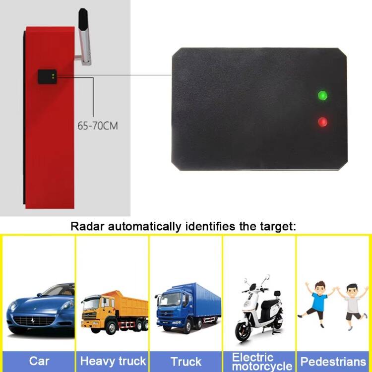
Detects trucks, cars forklifts & even motor bikes and personnel.
--Parking garage/lot detection;
--Exhibition hall security;
--Building parking charges
--Access control system
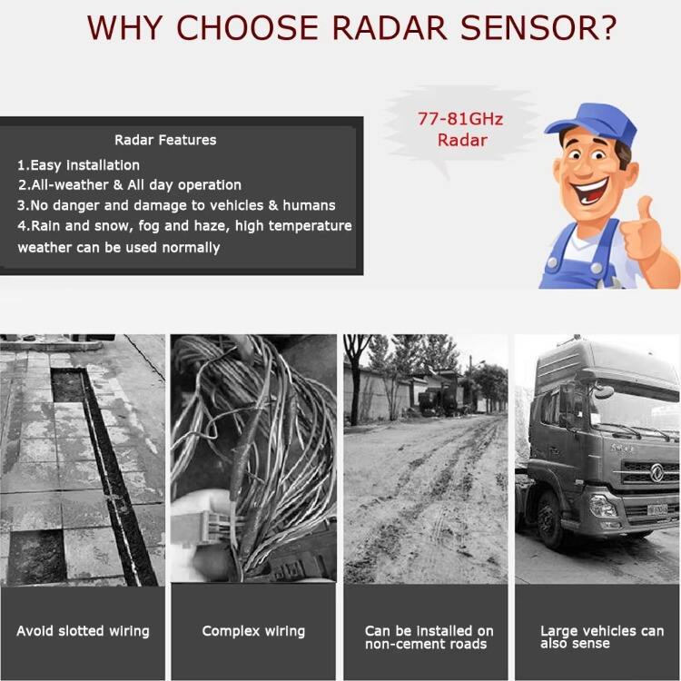
Are you still troubled to install loop detector and loops?
1) Cutting ground-Waste time and not good looking;
2) Complex wiring-Messy and Difficult;
3) Mud road-Cannot fix the loop;
4) Cannot detect big truck, trailer or other vehicles with high-bed.
Why choose barrier radar detector?
1) Can replace loop detector completely; no wiring layout, save time and cost.
2) Easy installation; Easy parameters setting; Adjustable distance from 1 to 6m.
3) Work in range of 77-81Ghz without effects from any climatic environment.
4) Can effectively distinguish vehicles and humans to avoid any hitting.
| Specification | Parameter | Technical index |
| System properties | Supply voltage | 10~16V |
| Operating temperature | -40~+85℃ | |
| Power consumption | <2.5W | |
| Waterproof rate | IP67 | |
| Communication interface | TTL | |
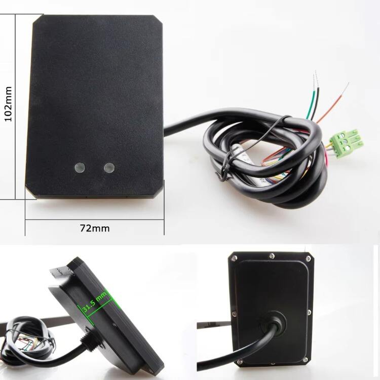
| Product size | 102 *72 * 31.5 (mm) | |
| Detection range | Lateral width | Standard ±0.5m(can be configured ±1m) |
| Longitudinal length | Standard 3m(can be configured 6m) | |
| Upgrade debugging |
Online debugging |
Serial Port Debugging |
|
Online upgrade |
Serial Port upgrade |
Cable Connector Description:
| NO | CABLE ID | Color | Description |
| 1. | VCC | Red | Positive pole |
| 2. | GND | Black | Negative pole |
| 3. | GND | Yellow | Reserved Ground |
| 4. | A+ | White | RX |
| 5. | B- | Gray | TX |
| 6. | J1 | Brown | Gate control signal (gate closed) |
| 7. | - | Blue | Public common signal of barrier gate |
| 8. | J2 | Green | Gate control signal (gate open) |

|
Installation Instructions: |
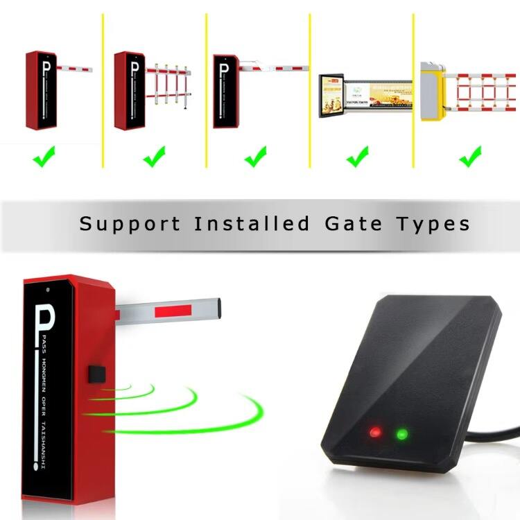
Range scope setting of the ITS-A06 radar can be achieved through the following ways: Manual Self-Learning Setting and Host Software Setting. Clients can choose suitable and convenient setting way.
· Manual Self-Learning Setting
Radar working mode and range scope can be configured automatically by walking around in front of the radar FOV(Field Of View) according to the type of gate.
Operation Steps:
· For Straight-bar or Fence Gate
(1) Trigger the dial switch to state ”ON”.
(2) Connect the radar to the power supply, and the LED indicator on the surface of radar begins to blink after 3 seconds after power on, which indicates that the radar is working on the self-learning mode.
(3) Client is required to keep walking from radar to the end of the gate bar back and forth UNTIL the blinking green LED stops twinkling and keeps on. Then the range scope will be set to stable maximum range along the radar normal direction. (Currently the maximum configurable range is 6 meters).
(4) When the green light is on, trigger the dial switch back to the original position, and the radar can work normally after power off and restart.
· For Advertisement Gate
(1) Trigger the dial switch to state ”ON”.
(2) Connect the radar to the power supply. Trigger the dial switch back to the original position at least 1 second later after the power on. The LED indicator on the surface of radar begins to blink after 3 seconds after power on, which indicates that the radar is working on the self-learning mode.
(3)Client is required to keep walking from radar to the end of the gate bar back and forth UNTIL the blinking green LED stops twinkling and keeps ‘OFF’. Then the range scope will be set to stable maximum range along the radar normal direction. (Currently the maximum configurable range is 6 meters).
4.When the green light is off, the radar can work normally after power reset.
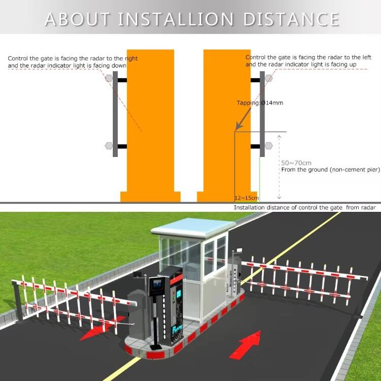
Attentions: ITS-A06 barrier radar must be installed 12-15 cm from the fence rail and 50-70 cm from the ground, as shown in the figure:


Copyright © 2024 Dongguan Kysail Tech LTD. All Rights Reserved